
01 / The research
A portable game set, made from measured material
The first-stage games plan selects three quiet table games and three outdoor sets. This workshop builds a twelve-bowl Oware tray, a nine-position Mū tōrere board and a 24-node Morris board, then provides six individual storage plans. These are portable tabletop projects, not seats, steps, toys certified for children or permanent outdoor structures.
Prefer a flat, known-history panel for the playing surface. Sound reclaimed plywood or a sound flat furniture panel can be suitable after inspection; do not glue random pallet slats into a precision board without addressing flatness and joint movement. Pallet boards can form assessed light rims and box sides. Reject unknown coatings, contamination, rot and hidden metal before any cutting. The pallet and material-intake guides provide the preparation method.
Use a tape, square, pencil, straightedge and a paper layout first. Add clamps, a suitable supported saw, a drill/driver if the rim uses mechanical connections, sanding with extraction and a finish suited to this indoor object. Select screws for actual thickness and connections so tips do not emerge. New fixings and a small known suitable base panel are legitimate parts of a reclaimed project.
Measurements below are illustrative workshop layouts, not historic standard board dimensions. Keep a full-size paper template, board ID and measured cut list for each set. Dry-fit with the actual pieces before finishing. For guest use check the table, seating, reach and loose-counter risks. No new audio, filming, purchase or physical build is implied.
02 / The research
Oware: a twelve-bowl tray without routing deep holes
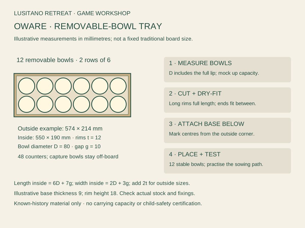
Use twelve identical stable removable bowls arranged in two rows of six, with two additional capture bowls kept off the sowing circuit. Count 48 smooth counters. Test the bowls with more than the four starting counters: play can accumulate a large pile in one pit, and the chosen bowls must remain usable. Measure maximum outside bowl diameter D, including lips, and the tallest bowl before sizing the tray. [G1]
Choose a measured clear gap g between bowls and between the bowls and the inside rim. For identical bowls, clear interior length = 6D + 7g; clear interior width = 2D + 3g. With measured rim thickness t, outside base length = clear length + 2t; outside width = clear width + 2t. Example only: D=80, g=10, t=12 mm gives an outside base of 574 × 214 mm and clear interior 550 × 190 mm. Bowls and counters determine the final dimensions.
Cut the known suitable base to the outside footprint. For this example use a 9 mm panel only if it remains adequately flat and supported for the intended tabletop use; no carrying or unsupported-span capacity is asserted. Cut two full-length rims 574 × 18 × 12 mm and two end rims 190 × 18 × 12 mm. End rims fit BETWEEN the long rims; base is attached UNDER the frame. Actual bowl height may exceed the low rim.
Dry-fit on a level bench. Compare the frame diagonals, mark joints in sound wood and secure the frame using suitable joints and new fixings for the measured stock. Attach the base beneath the rim, fixing into sound rim material rather than the open interior. Clamp and pre-drill as appropriate; inspect every underside tip before turning it over.
Mark bowl centres from the OUTSIDE top-left corner of this example base: x = 62,152,242,332,422,512 mm; y = 62 and 152 mm. In the general formula, x = t+g+D/2+i(D+g), i=0…5; y = t+g+D/2+j(D+g), j=0…1. Test all twelve real bowls at these positions before marking permanent circles. A larger lip or non-round bowl requires a new layout.
Use a removable appropriate non-slip liner or individually fitted removable locating pads to keep bowls steady; do not improvise protruding metal clips. Keep the bowls removable for cleaning and inspection. Label the two player rows discreetly and add the sowing direction using the chosen teaching diagram; capture bowls sit separately and are never sown into.
Sand and ease contact edges, remove dust and apply only a suitable finish following its cure instructions. Put four counters in every bowl, demonstrate the anticlockwise path and test lifting/sowing/capturing without neighbouring bowls moving. Reject wobbling bowls or a tray that rocks. Store all 48 counters in a labelled closed pouch after play.
| Example component | Quantity | Cut or supply |
|---|---|---|
| Known suitable base | 1 | 574 × 214 × 9 mm example |
| Long rims | 2 | 574 × 18 × 12 mm |
| End rims, between long rims | 2 | 190 × 18 × 12 mm |
| Playing bowls | 12 | Actual D=80 mm assumed only for example |
| Capture bowls | 2 | Off the sowing circuit |
| Counters | 48 | Smooth, consistent and appropriate for users |
03 / The research
Mū tōrere: a measured nine-position board
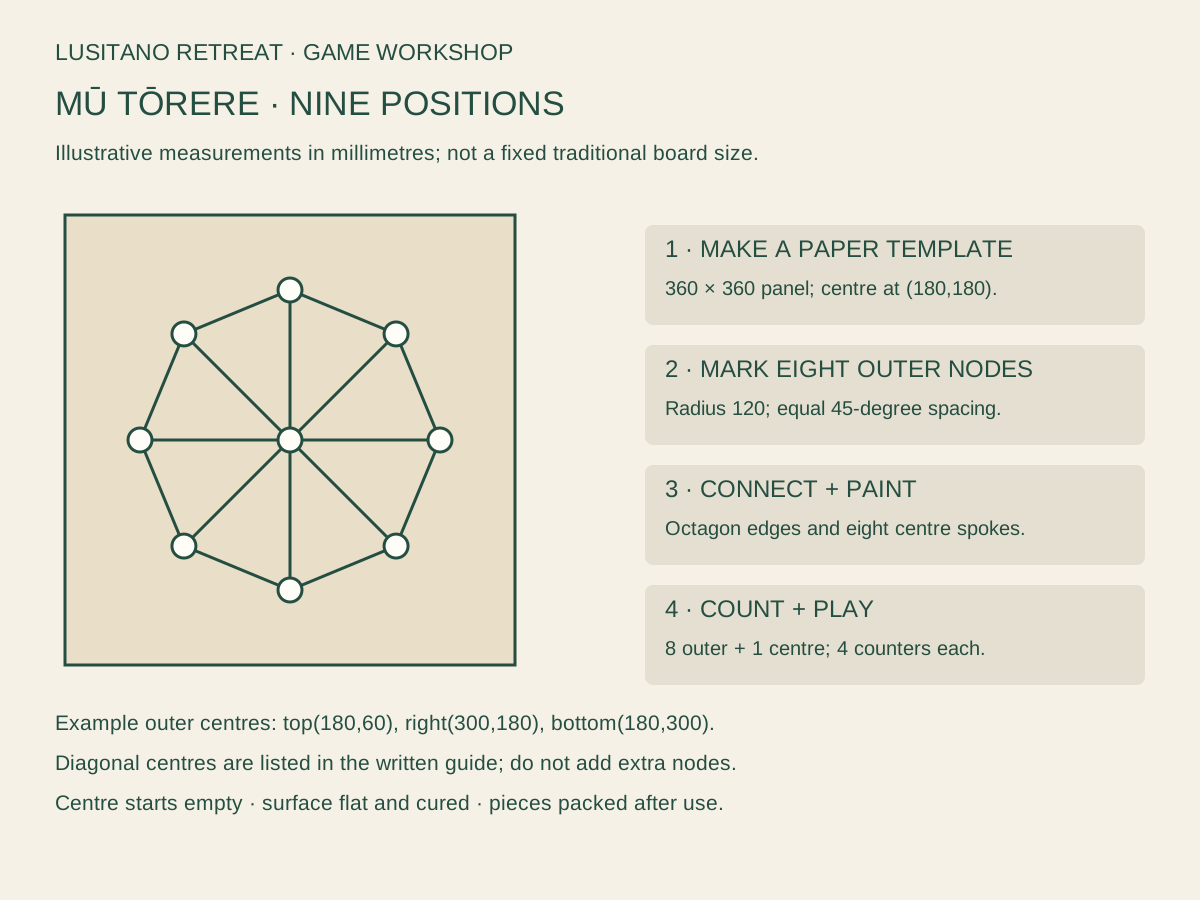
Make a square portable board, illustratively 360 × 360 mm, from a flat known suitable panel. The eight outer positions are called kewai and the centre pūtahi. Use four counters of each colour, with the centre empty at setup. The eight-position geometry matters; the 360 mm size is our workshop choice, not a traditional fixed measurement. Follow the selected teaching rules linked in the games library. [G2]
Choose and measure the actual counters before marking. A circular counter approximately 25 mm in diameter suits the illustrated spacing, but size is a proposed usability example, not a small-parts safety certificate. Keep the pieces distinct in colour and texture where useful, and check that a player can pick up a counter without moving its neighbour.
Cut and check the 360 mm square panel on a supported bench. Ease the four corners and all edges, inspect both faces and check flatness on the intended table. Use a paper template to mark a centre at (180,180) mm, measured from the top-left corner.
Place eight outer centres on a radius of 120 mm: clockwise from top, (180,60), (264.9,95.1), (300,180), (264.9,264.9), (180,300), (95.1,264.9), (60,180), (95.1,95.1). The diagonal coordinates are rounded to 0.1 mm for the paper layout; equal angular spacing matters more than implying machine precision.
Draw lines joining neighbouring outer centres into an octagon, then eight lines from the outer centres to the middle. Mark a clear playing circle at each of the nine centres. Do not add extra stops along the spokes: the game has exactly nine positions, not every crossing of a decorative pattern.
Dry-fit four pieces on four consecutive outer positions and the other colour on the remaining four. Leave the middle empty. Test the chosen legal move from a boundary counter into the centre; use a separate removable arrow card for teaching rather than permanently drawing an extra playing piece in the centre.
Paint the lines and node circles with contrasting suitable coating, preserving legibility under the intended light. Let it fully cure. Add non-slip feet suitable for the table, fitted without sharp tips, and label the reverse with board ID, piece count and the chosen variant.
Before use, count eight outer nodes plus one centre, trace every connection, confirm the middle is not an extra counter and check surface snagging with a cloth. Pack the eight counters in a labelled pouch; inspect the panel for warp, loose feet and finish damage after storage.
| Component | Quantity | Example layout |
|---|---|---|
| Flat panel | 1 | 360 × 360 mm; thickness selected from actual stock |
| Outer playing positions | 8 | Radius 120 mm about centre (180,180) |
| Centre position | 1 | (180,180) mm |
| Counters | 8 | 4 each of two distinct colours |
| Non-slip feet / pouch | As suitable | No exposed fasteners |
04 / The research
Nine Men’s Morris: twenty-four nodes, no diagonals
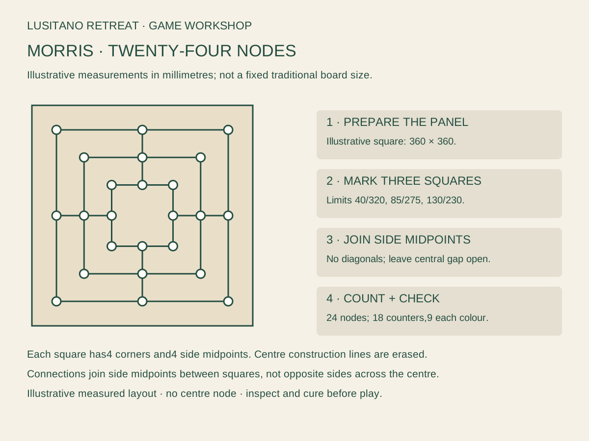
Use a separate flat square panel, illustratively 360 × 360 mm, and eighteen counters, nine of each colour. This creates the board for the three-phase game already documented in our rules library. Nodes are the corners and side midpoints of three squares; decorative line crossings are not additional spaces. [G3]
Select the actual pieces before cutting. Check their contrast and finger clearance on a paper model. A proposed counter diameter around 25 mm leaves useful separation in this example, but adapt the board if the actual users need larger pieces or easier grip. Do not claim a counter size is safe for unsupervised young children.
Cut, smooth and inspect the square panel, checking flatness on the intended table. Draw a light removable pencil centreline horizontally and vertically at 180 mm. Mark outer square corners at (40,40),(320,40),(320,320),(40,320); middle square corners at (85,85),(275,85),(275,275),(85,275); inner square corners at (130,130),(230,130),(230,230),(130,230).
Add each square’s four side midpoints. These are top/bottom at x=180 mm and left/right at y=180 mm. The outer node coordinates use 40/180/320, middle 85/180/275, inner 130/180/230. This gives eight nodes per square and exactly twenty-four overall.
Join adjacent nodes around each square. Connect the aligned side midpoints between squares: top along x=180,y40→130; bottom x=180,y230→320; left y=180,x40→130; right y=180,x230→320. Leave the central space empty. Do not connect square corners diagonally or draw a line across the central gap.
Mark node circles clearly, then lay three counters along one outer straight side to demonstrate a mill. Move a counter along one drawn edge to an adjacent node and check that the line network is readable. Erase the centre construction lines before painting permanent marks.
Apply the chosen suitable finish with the board flat and allow complete curing. Fit appropriate non-slip feet and identify the game on the reverse with 18-piece inventory and a link to the chosen rules. Do not permanently fix the demonstration mill pieces to the board.
Count all 24 nodes and trace each connection with the printed diagram. Check that the central gap remains unconnected, pieces rest evenly and no coating catches a cloth. Pack nine counters of each colour; repeated-position draw and flying-at-three are rules choices, not modifications to the board.
| Square | Corner limits (mm) | Four midpoint positions |
|---|---|---|
| Outer | 40…320 | Top/bottom x180; sides y180 |
| Middle | 85…275 | Top/bottom x180; sides y180 |
| Inner | 130…230 | Top/bottom x180; sides y180 |
| Count | 3 × 8 = 24 nodes | No diagonals; no central node |
| Pieces | 18 counters | 9 per colour |
05 / The research
Mölkky: a divided pin store
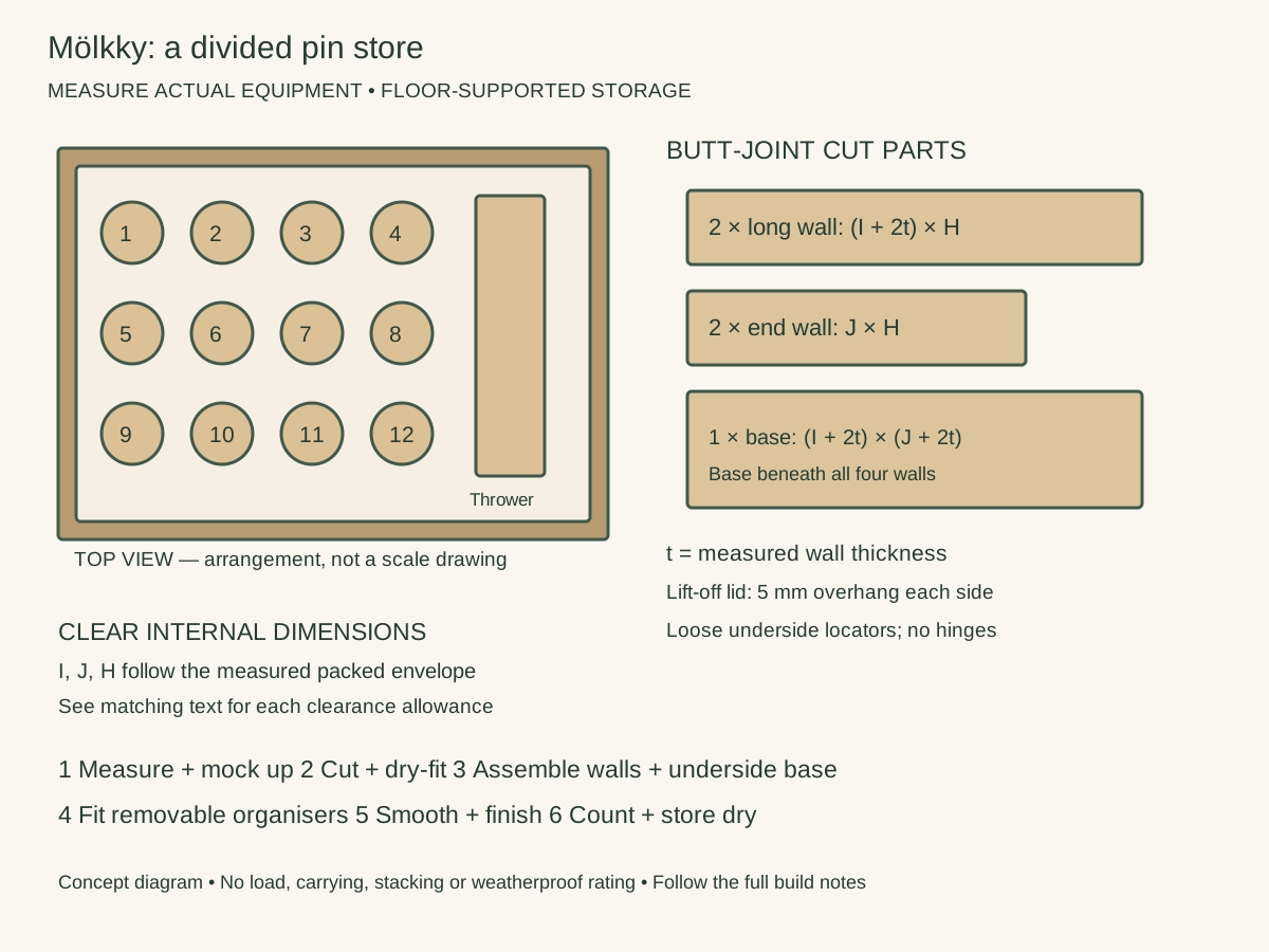
Arrange the 12 numbered pins upright in three rows of four and lay the throwing skittle beside them. Measure that complete arrangement rather than borrowing dimensions from another brand. Make a cardboard divider mock-up so every sloping pin top stays below the lid.
Measure the packed equipment first: A is its longest horizontal envelope, B the other horizontal envelope and C its height, including any liner. Include every proposed partition thickness in A and B: use full-thickness scrap spacers in the mock-up, not paper-thin divider lines. Choose actual sound stock thickness t. For the butt-jointed box described here, long walls run the full outside length; end walls fit between them; the base sits underneath all four walls. Thus outside length L = inside length I + 2t and outside width W = inside width J + 2t. Cut two long walls L × H, two ends J × H, and one base L × W. Clear internal height is H; the base adds its own thickness below. Use known-source dry timber or suitable plywood, remove metal and reject contamination; a heat-treatment stamp alone does not establish suitability. These are floor-supported stores, without carrying or stacking claims. A lift-off cap’s shallow locator strips fit loosely INSIDE the box opening, clear of contents, not around the outside walls.
I = A + 20 mm; J = B + 20 mm; H = C + 15 mm.
- 1. Count 12 pins and one throwing skittle; measure the dry packed arrangement and mark I, J and H on a sketch.
- 2. Cut the five outer pieces using the common butt-joint formula. Dry-fit on a flat bench and compare the two diagonals before fastening.
- 3. Assemble the four walls, then fix the base beneath their edges. Choose fastener diameter, length and pilot holes for the actual stock so no point enters the storage space.
- 4. Add two removable longitudinal divider strips to create three pin rows. Measure each strip between the end walls; set its height below the shortest pin top so fingers can reach the pins.
- 5. Fit a separate low divider around the throwing skittle, using its actual envelope. Keep partitions removable: they organise pieces and are not structural braces.
- 6. Smooth every accessible edge and remove sanding dust. Apply a finish suitable for the timber and intended dry storage; allow full curing before packing.
- 7. Make a lift-off cap with a flat top L+10 × W+10 mm and four shallow underside locator strips fitted loosely inside the clear opening. Check that it lifts without gripping the pins.
- 8. Label 1–12 and a throwing-skittle position. Check for trapped moisture after outdoor play, dry each piece separately and store the box on a dry floor.
06 / The research
Cornhole: two flat board boxes and a bag box
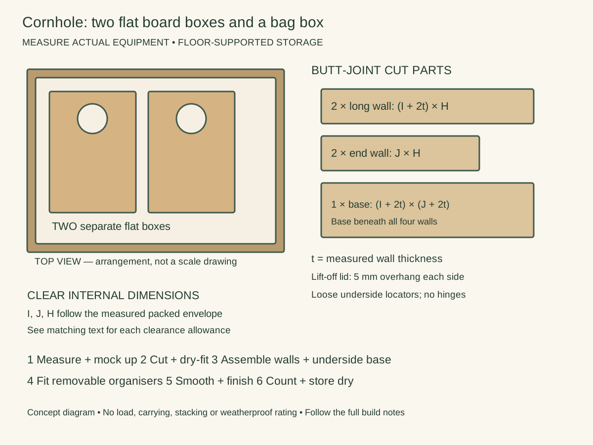
Make one shallow floor box for each of the two actual folded cornhole boards. Store the eight bags separately. The boards lie flat; this is not a standing rack. Measure the folded legs, feet, hinges and any projecting hardware as part of the equipment envelope.
Measure the packed equipment first: A is its longest horizontal envelope, B the other horizontal envelope and C its height, including any liner. Include every proposed partition thickness in A and B: use full-thickness scrap spacers in the mock-up, not paper-thin divider lines. Choose actual sound stock thickness t. For the butt-jointed box described here, long walls run the full outside length; end walls fit between them; the base sits underneath all four walls. Thus outside length L = inside length I + 2t and outside width W = inside width J + 2t. Cut two long walls L × H, two ends J × H, and one base L × W. Clear internal height is H; the base adds its own thickness below. Use known-source dry timber or suitable plywood, remove metal and reject contamination; a heat-treatment stamp alone does not establish suitability. These are floor-supported stores, without carrying or stacking claims. A lift-off cap’s shallow locator strips fit loosely INSIDE the box opening, clear of contents, not around the outside walls.
For EACH board: I = A + 30 mm; J = B + 30 mm; H = C + 20 mm. Bag box uses its measured eight-bag envelope plus 20 mm horizontally and 15 mm vertically.
- 1. Fold each board exactly as its maker permits, without forcing a hinge. Measure its own A, B and C; make separate labels if the two boards differ.
- 2. Lay out one base and four walls per board using the common formula. A large base needs material suitable for floor-supported storage; do not assume thin pallet slats form a continuous protective panel.
- 3. Dry-fit each box and check the board can be removed by two adults using its intended lifting points. The storage box itself has no lifting rating.
- 4. Assemble walls and base, keeping all screw tips clear. Fit a removable, dry soft liner on the base; no liner should catch on folded legs or hardware.
- 5. Add small removable corner pads only where they cannot press on the playing surface. Leave enough hand space to lift the board; increase clearance if 15 mm per side is insufficient.
- 6. Make a loose lift-off cover to the outside footprint with a 5 mm overhang on each edge. Locate it with shallow underside strips; avoid hinges or catches that could scratch the board.
- 7. Build a separate five-piece bag box around all eight dry bags, following the smaller-box envelope formula. Label two sets of four and provide a simple inventory card.
- 8. Place both board boxes flat in separate floor positions, without stacking. Dry bags and boards before closing. Confirm the storage area keeps exits clear; a lid is dust protection, not a weatherproof enclosure.
07 / The research
Soft quoits: ring tray with a removable peg channel
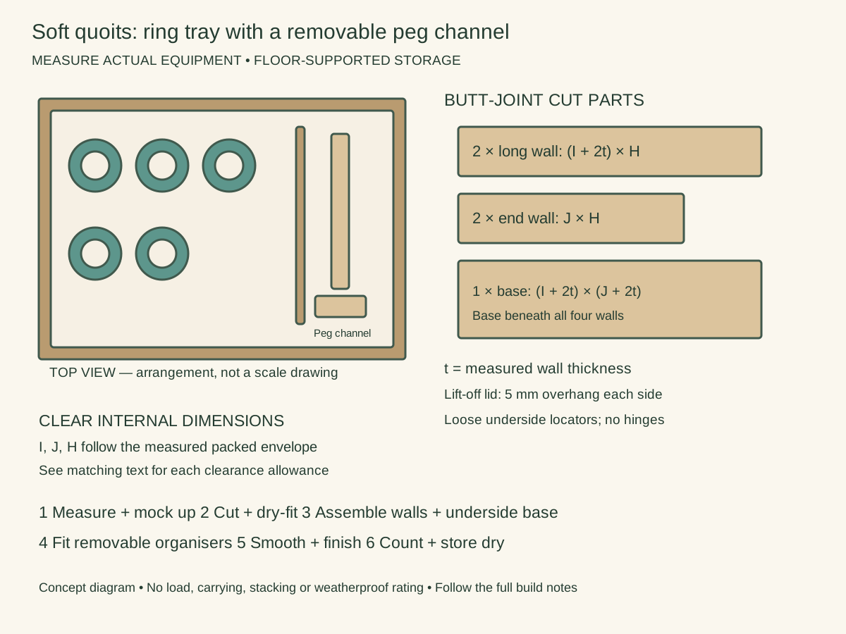
Lay the five soft rings flat in the arrangement that avoids distortion. Put the target peg and its detachable base beside them, only disassembling parts designed to separate. A removable internal channel keeps the peg from rubbing the rings.
Measure the packed equipment first: A is its longest horizontal envelope, B the other horizontal envelope and C its height, including any liner. Include every proposed partition thickness in A and B: use full-thickness scrap spacers in the mock-up, not paper-thin divider lines. Choose actual sound stock thickness t. For the butt-jointed box described here, long walls run the full outside length; end walls fit between them; the base sits underneath all four walls. Thus outside length L = inside length I + 2t and outside width W = inside width J + 2t. Cut two long walls L × H, two ends J × H, and one base L × W. Clear internal height is H; the base adds its own thickness below. Use known-source dry timber or suitable plywood, remove metal and reject contamination; a heat-treatment stamp alone does not establish suitability. These are floor-supported stores, without carrying or stacking claims. A lift-off cap’s shallow locator strips fit loosely INSIDE the box opening, clear of contents, not around the outside walls.
I = A + 20 mm; J = B + 20 mm; H = C + 15 mm. If the peg stays assembled, C must include its full height; do not saw it shorter.
- 1. Count five soft rings and the complete target. Check how the target packs according to its maker and measure the resulting envelope.
- 2. Mock up a ring area and a peg channel with cardboard. Keep the channel wide enough to remove the peg without bending a ring.
- 3. Cut the five outer parts from the common formula, using the chosen actual thickness. Mark long walls and between-wall ends so the thickness is not counted twice.
- 4. Clamp and dry-fit, then assemble the walls and base. Select fasteners for the joint and material; countersink only as appropriate and leave no sharp exposed points.
- 5. Cut a removable channel divider to the measured distance between end walls. Secure it with small internal locating blocks, positioned outside the equipment envelope; the divider can lift out for cleaning.
- 6. Smooth the contact faces. Use a loose, washable liner compatible with the ring material and keep it clear of sharp fittings; do not compress or tightly tie soft rings into a smaller box.
- 7. Make a loose cap with 5 mm overhang all around and underside locator strips. Test opening with the target packed, checking that the lid neither touches the peg nor squeezes the rings.
- 8. Mark five ring positions and one target position. Dry the target and rings after play, inspect ring splits and peg damage, and place the store on a dry floor. This box is not a target stand or a child seat.
08 / The research
Oware: bowl compartments and a separate counter pot
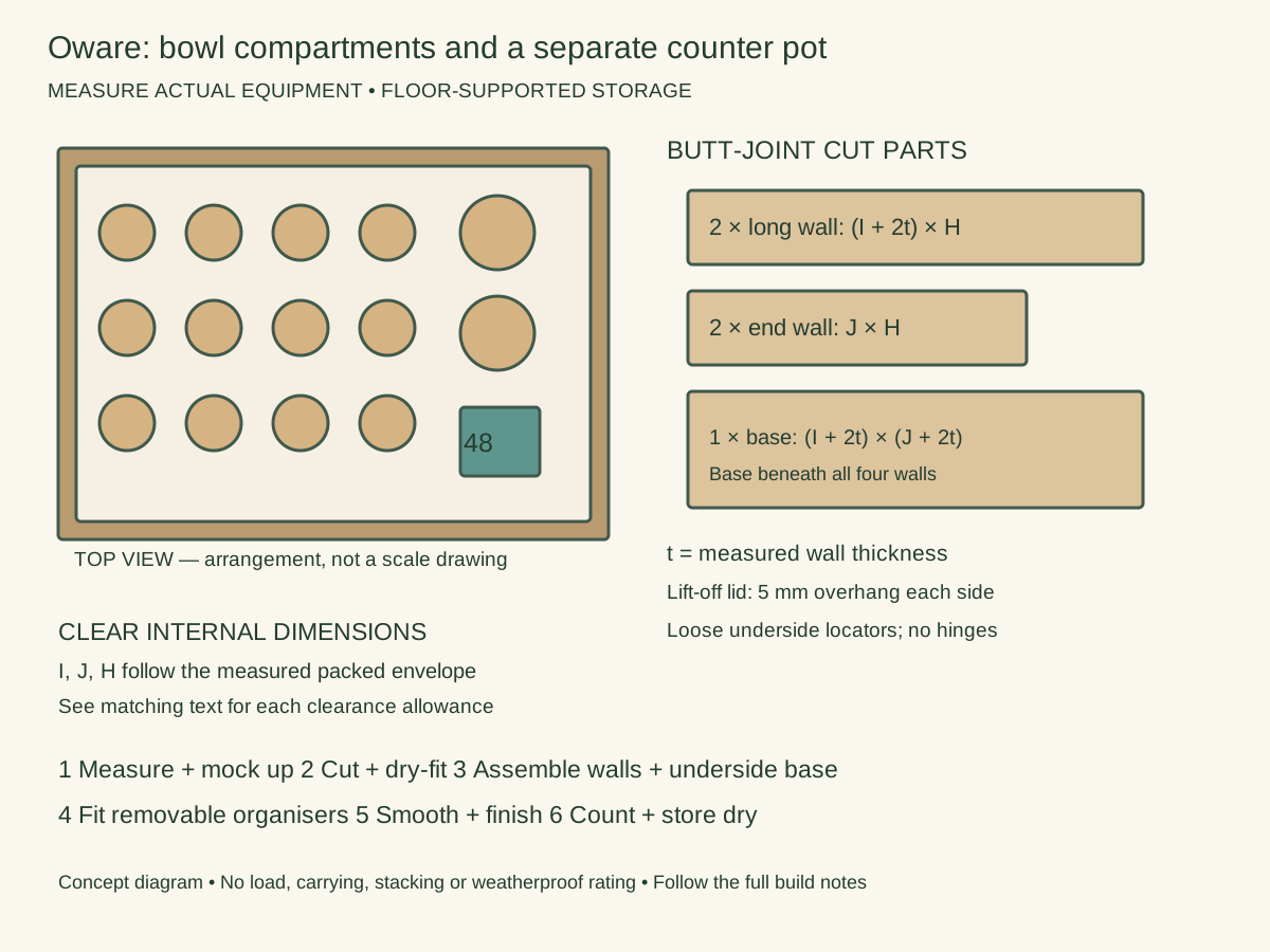
This store holds the selected removable-bowl Oware tray, 12 playing bowls, two capture bowls and 48 counters. If bowls remain fixed to the board, measure that assembly instead and omit the loose-bowl compartments. Count counters into two labelled groups of 24 for inventory; that count is storage, not the opening position.
Measure the packed equipment first: A is its longest horizontal envelope, B the other horizontal envelope and C its height, including any liner. Include every proposed partition thickness in A and B: use full-thickness scrap spacers in the mock-up, not paper-thin divider lines. Choose actual sound stock thickness t. For the butt-jointed box described here, long walls run the full outside length; end walls fit between them; the base sits underneath all four walls. Thus outside length L = inside length I + 2t and outside width W = inside width J + 2t. Cut two long walls L × H, two ends J × H, and one base L × W. Clear internal height is H; the base adds its own thickness below. Use known-source dry timber or suitable plywood, remove metal and reject contamination; a heat-treatment stamp alone does not establish suitability. These are floor-supported stores, without carrying or stacking claims. A lift-off cap’s shallow locator strips fit loosely INSIDE the box opening, clear of contents, not around the outside walls.
I = A + 20 mm; J = B + 20 mm; H = C + 15 mm. Measure the complete board, bowls and closed counter pot in their intended packed arrangement.
- 1. Put the actual tray and all 14 bowls on paper. Trace the packed layout; do not assume commercial bowls share diameter, height or safe nesting behaviour.
- 2. Select a small lidded counter pot that contains all 48 counters without pressure on its lid. Place it beside the bowls and measure the complete A, B and C envelope.
- 3. Cut base and walls using the common formula. Dry-fit the tray in the open box with the intended liner before committing to the joints.
- 4. Assemble the walls and underside base, checking squareness and hidden fastener ends. Keep the box floor-supported and remove equipment before repositioning it.
- 5. Make a removable divider grid from measured strips. One strip separates the counter pot; others separate bowl groups. Cut halfway-depth crossing slots only in these non-loadbearing dividers, sized to their actual thickness.
- 6. Sand dividers and contact edges smooth. Leave finger access around each bowl; if nesting is unsuitable, allocate individual positions and enlarge the box rather than forcing the layout.
- 7. Fit a loose cap with a 5 mm overhang on every side and shallow underside locators. Let any coating fully cure; the storage finish does not certify food-contact suitability.
- 8. Label 12 playing bowls, two capture bowls and 48 counters. Pack only dry pieces, check missing counters before the next session and keep small counters away from unsupervised young children. Include the selected rules card in a separate dry envelope.
09 / The research
Mū tōrere: square-board sleeve box
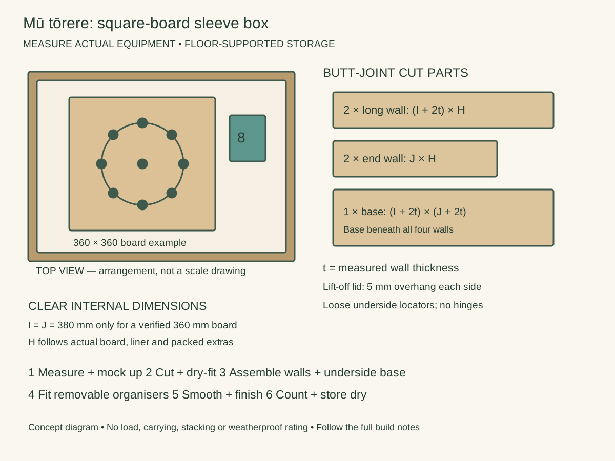
For the proposed 360 × 360 mm flat board, use a shallow square box with a removable lid, two broad pull-out fabric tabs and a separate lidded pot for eight counters. The tabs help lift the board inside the box; they are not box-carrying handles. Measure the finished board before cutting.
Measure the packed equipment first: A is its longest horizontal envelope, B the other horizontal envelope and C its height, including any liner. Include every proposed partition thickness in A and B: use full-thickness scrap spacers in the mock-up, not paper-thin divider lines. Choose actual sound stock thickness t. For the butt-jointed box described here, long walls run the full outside length; end walls fit between them; the base sits underneath all four walls. Thus outside length L = inside length I + 2t and outside width W = inside width J + 2t. Cut two long walls L × H, two ends J × H, and one base L × W. Clear internal height is H; the base adds its own thickness below. Use known-source dry timber or suitable plywood, remove metal and reject contamination; a heat-treatment stamp alone does not establish suitability. These are floor-supported stores, without carrying or stacking claims. A lift-off cap’s shallow locator strips fit loosely INSIDE the box opening, clear of contents, not around the outside walls.
Illustrative clear inside I = J = 380 mm for a confirmed 360 mm square board. H = actual board thickness + liner thickness + 15 mm removal clearance; increase H if the counter pot is taller.
- 1. Check that the finished board really measures 360 mm square. If it differs, replace both 380 mm clear dimensions with actual board dimensions plus at least 20 mm total clearance.
- 2. Measure thickness and the chosen liner, then select a counter pot. Decide whether the pot sits beside the board in an enlarged box or above it with a removable separator; include the full packed height.
- 3. Cut two walls (380+2t) × H, two ends 380 × H and base (380+2t) square for the stated example. Confirm t from the actual material.
- 4. Dry-fit, compare diagonals and assemble the walls and underside base. Choose fixing lengths from the real joint so tips cannot mark the board.
- 5. Lay two broad fabric tabs across the base under the loose liner, with ends accessible at opposite edges. They lift the board gently; do not permanently glue them onto its playing surface.
- 6. Fit a removable separator above the board if using overhead counter storage. Support it on four small corner blocks clear of the board; its top and counter pot must remain below the lid.
- 7. Make a cap with 5 mm overhang around the box and shallow loose-fitting underside locators. Smooth and finish all edges, keeping soft material away from wet coatings.
- 8. Label four counters of each colour and the board with eight outer points and one centre. Check that the board can be lifted without bending, count all eight counters and place the box flat on a dry floor. Keep the printed rules dry and separate from the playing face.
10 / The research
Nine Men’s Morris: board box with two counter wells
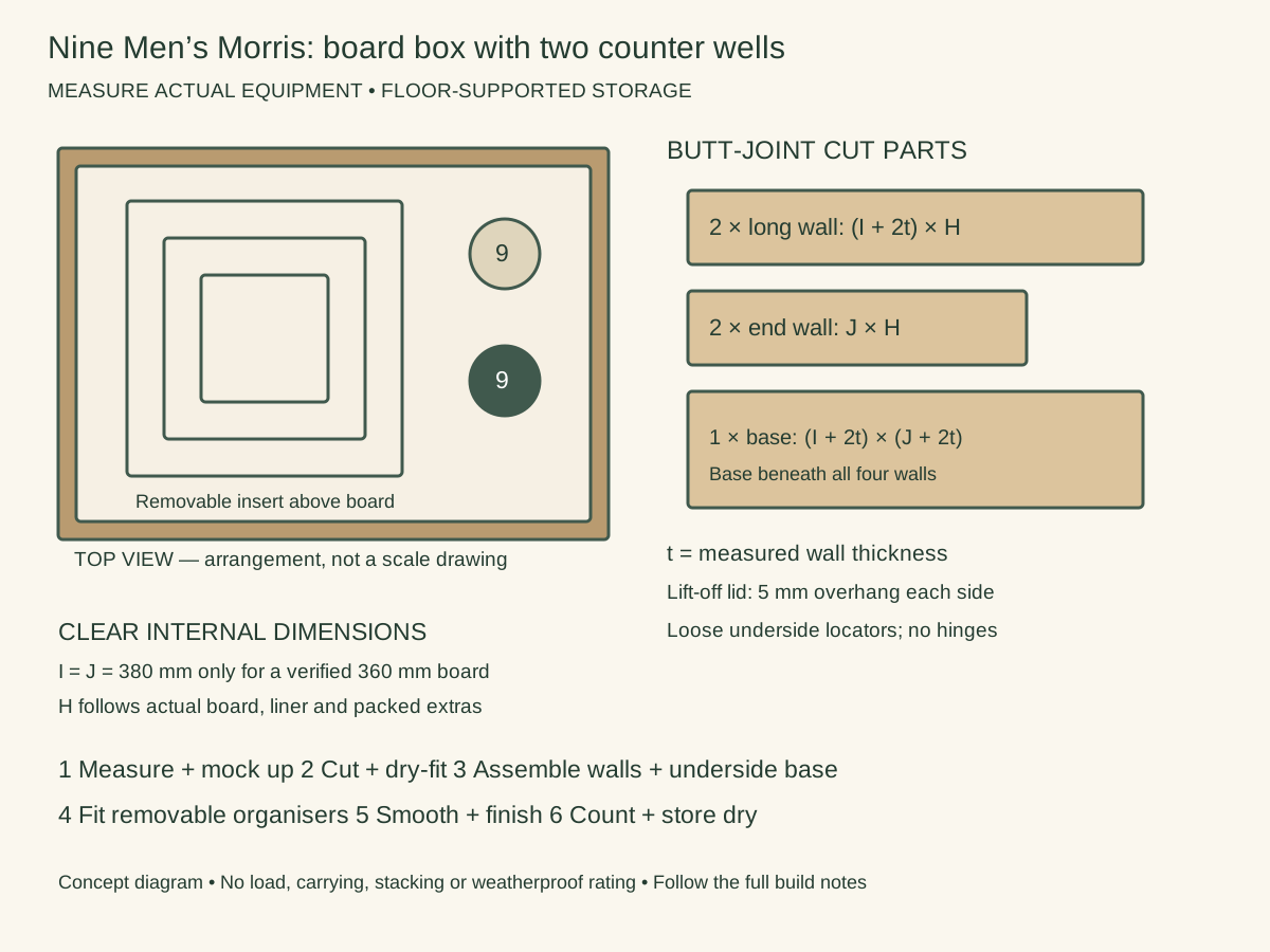
Use the proposed 360 × 360 mm board in a shallow square floor box, with a removable upper insert containing two lidded counter pots. Each pot holds one set of nine. The insert separates loose equipment from the board surface; do not cut storage pockets into the playing board.
Measure the packed equipment first: A is its longest horizontal envelope, B the other horizontal envelope and C its height, including any liner. Include every proposed partition thickness in A and B: use full-thickness scrap spacers in the mock-up, not paper-thin divider lines. Choose actual sound stock thickness t. For the butt-jointed box described here, long walls run the full outside length; end walls fit between them; the base sits underneath all four walls. Thus outside length L = inside length I + 2t and outside width W = inside width J + 2t. Cut two long walls L × H, two ends J × H, and one base L × W. Clear internal height is H; the base adds its own thickness below. Use known-source dry timber or suitable plywood, remove metal and reject contamination; a heat-treatment stamp alone does not establish suitability. These are floor-supported stores, without carrying or stacking claims. A lift-off cap’s shallow locator strips fit loosely INSIDE the box opening, clear of contents, not around the outside walls.
Illustrative clear inside I = J = 380 mm after confirming the board is 360 mm square. H = lined board height + separator thickness + tallest closed pot height + 15 mm free clearance.
- 1. Measure the finished board and the two closed pots. For a different board size, use its actual horizontal dimensions plus 20 mm total clearance instead of the illustrative 380 mm square interior.
- 2. Draw a side section showing base, loose liner, board, separator and pots. Add those real thicknesses before cutting H; there must be space above the closed pots.
- 3. Cut two long walls (380+2t) × H, two ends 380 × H and a (380+2t) square underside base for the example. Record actual t and base thickness separately.
- 4. Dry-fit and assemble the box square. Use suitable new fixings and pilot holes for the material; inspect the interior for screw points and split edges.
- 5. Fit four small corner supports above the lined board height. Make a removable separator that clears the walls without binding, with a finger notch for removal; fit no supports onto the playing board.
- 6. Position two nine-counter pots on the separator. Add low removable locating strips around their footprints, leaving hand clearance. These keep pots apart, not secure them for transport.
- 7. Add a loose cap with a 5 mm overhang around all sides and shallow underside locators. Sand, clean and allow any compatible finish to cure before installing the liner and equipment.
- 8. Count nine light and nine dark counters, label the two pots and include the chosen rules card. Test removal of the insert and board in sequence. Store flat on a dry floor, keep the lid free of other boxes and inspect for damp before closing.
11 / The research
Check, label and teach before adding more sets
Use a paper layout first, then make one prototype and play a full practice game with the actual pieces. Keep the work record: accepted timber source, final sizes, new components, finish and cure date, any altered part and the check outcome. Correct a moving bowl, unclear connection or warped board before guest use.
The six storage plans serve the proposed pilot inventory, not every future set. Keep dry components together with their rules, count parts after play and remove faulty pieces. Suitable storage and large contrasting playing pieces can make sessions easier, but accessibility depends on the people and table arrangement.
For a future episode, show measurement, rejection of unsuitable wood, paper layout, dry fit, finished checks and the first genuine game. The 21 chapters remain a narrative structure; no build or filming deadline is implied.